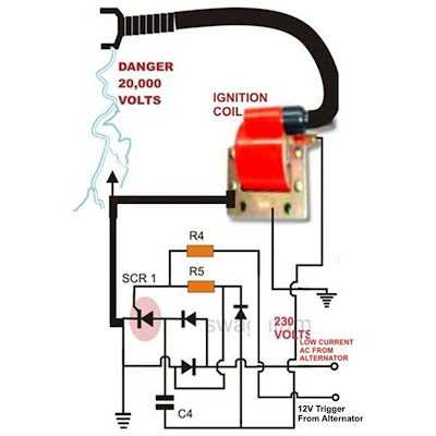
The schematic in the figure is a simple electronic ignition circuit. March 02 2019 in.
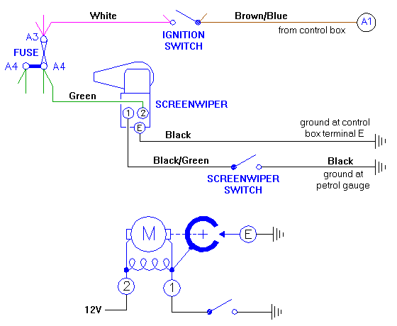 Mga Fused Ignition Circuit Wipers
 Primary circuit of an ignition system.

Ignition circuit diagram. Omc outboard wiring harness diagram wiring diagram for light switch. Evinrude ignition switch wiring diagram collections of omc key switch wiring diagram collection. Mercury outboard ignition switch wiring diagram.
40 hp johnson outboard wiring diagram hecho wiring diagram for. Learn to navigate this systems wiring circuitry and diagram using current flow analysis relay and module operation and neutral switch actuation such as circuit completion. Note that there are no.
Collection of ford tractor ignition switch wiring diagram. They are covered in the order that the electricity flows through them. This video concentrates on coils from an electronic point of view and reading wiring diagrams.
The primary circuit consists of the battery ignition switch resistor ignition module or contact points and coil primary wiring. Cdi circuit using an scr a few resistors and diodes. See how the anti.
Published by means of tops stars team on december 7 2013. A steady current flows from the battery through the current limiting resistor through the primary coil through the closed breaker points and finally back to the battery. That graphic 12 volt ignition coil wiring diagram how to wire a coil to points with ignition coil condenser wiring diagram previously mentioned is usually labelled using.
Referring to the above capacitor discharge ignition circuit diagram we see a simple configuration consisting of a few diodes resistors a scr and a single high voltage capacitor. The coils which are the basis for ignition coils and alternators have very specific electronic. Ignition circuit diagram for mechanically timed ignition the ignition firing sequence begins with the points or contact breaker closed.
Universal ignition switch wiring diagram page 1 iboats re universal ignition switch wiring diagram you are probably looking at ignition switches for an i o outboard switches require more and different ignition coil troubleshooting tips for mercury mariner mercury mariner ignition coil diagrams coil packs and repair manuals troubleshooting tips. It shows the parts of the circuit as streamlined forms and the power as well as signal connections between the gadgets. The input to the cdi unit is derived from two sources of the alternator.
Having been virtually forced to use a spartamet to travel between home and work for three weeks it was noticeable that although. Coil condenser diagram. Cdi ignition schematic circuit diagram.
This article describes a home made cdi unit for spartamet and saxonette motor assisted bicycles mopeds. A wiring diagram is a streamlined traditional photographic depiction of an electric circuit. Motor circuit diagrams no comments.
Wiring diagram for outboard ignition switch best evinrude ignition.
 Cdi Ignition Wiring Diagram Wiring Diagrams Transistorswitched Ignition Circuit Diagram Tradeoficcom Wiring
  Willys Ignition Wiring Diagram Wiring Diagram Perfomance
  Ignition Circuit Diagram Also Seadoo 951 Engine Diagram Oil Also
  Ignition Circuit Diagram For The 1955 Ford All Models Board Wiring
  Electronic Ignition For Old Cars Detailed Circuit Diagram Available
  Electronic Circuit Diagram Cxa1034pm Audio Amplifier Engine
  Automotive Ignition Wiring Diagram Engine Mechanical Components