Basic wiring for motor control technical data. Note that symbols are discussed in detail later.
 Electric Motor Contactor Wiring Schema Wiring Diagram
 Dashed lines indicate a single purchased component.

Basic motor control wiring diagram. If there are no convenient motor control circuit diagrams available for illustration you may want to ask a student to draw an across the line starter circuit on the whiteboard for everyone to see. It is also common for a control cabinet to supply a higher voltage to other equipment such as motors. Two wire control as seen in configuration 1 consists of a control device containing one set of contacts used to facilitate the on an off operation of a pilot device.
Wiring diagrams sometimes called main or construction diagrams show the actual connection points for the wires to the components and terminals of the controller. This video addresses the ways to protect the motor and the wire supplying it with power. An example of a wiring diagram for a motor controller is shown in figure 1.
Wiring diagrams show the connections to the controller. Wires between m1 control contact and control circuit broken open. In addition to motor control this vi.
Overcurrent protection for 3 wire control circuits 11 ac manual starters and manual motor. Basic electrical home wiring diagrams tutorials ups inverter wiring diagrams connection solar panel wiring installation diagrams batteries wiring connections and diagrams single phase three phase wiring diagrams 1 phase 3 phase wiringthree phase motor power control wiring diagrams. This unit discusses the basic concepts of motor control including motor control language and the types of wiring diagrams used.
Motor 3ct to 120 v separate control ot is a switch that opens when an overtemperature condition exists type mfo. 3 wire start stop. This video walks you through the basic 2 wire and 3 wire control for 3 phase motor controllers.
The basic control circuits include two wire three wire controls manual automatic sequential control stopstart forward reverse and jogging circuits. Three phase motor power control wiring diagrams 3 phase motor power control wiring diagrams three phase motor connection schematic power and control. Imagine trying to wire a.
Wiring diagram book a1 15 b1 b2 16 18 b3 a2 b1 b3 15 supply voltage 16 18 l m h 2 levels b2 l1 f u 1 460 v f u 2. Ac motor control circuits ac electric circuits. Motor control circuits motor control circuits are an effective way to reduce cost by using smaller wire and reduced amperage devices to control a motor.
 3 Phase Motor Diagram Wiring Diagram Review
  Circuit Diagram 3 Phase Motor Forward Reverse Wiring Diagram
 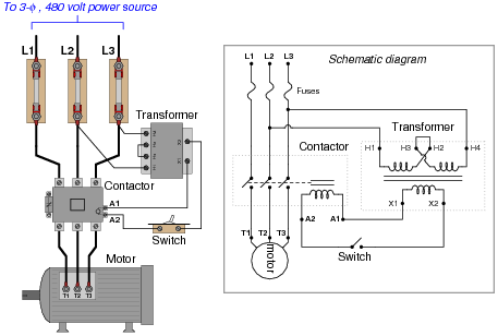 Ac Motor Control Circuits Ac Electric Circuits Worksheets
 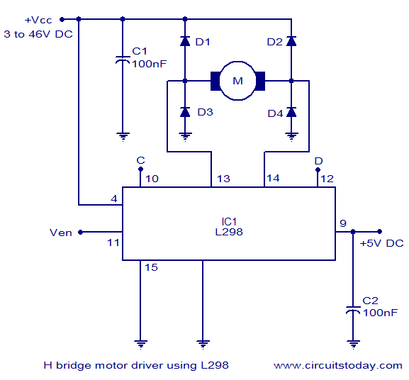 H Bridge Circuit Diagram Dc Motor Wiring Diagram
  Basic Wiring For Motor Control Technical Data Guide Eep
  Basic Motor Controls Diagrams Wiring Diagram Write
  3 Phase Motor Starter Wiring Diagram Pdf Beautiful 3 Phase To Single
  Basic Control Wiring Diagram Mncenterfornursing Com Ladder Diagram Basics 3 2 Wire 3 Wire Motor Control Circuit